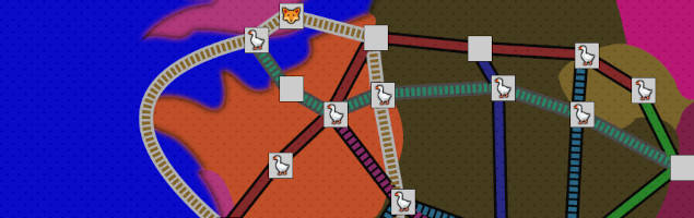


Exploring a 3D city with just HTML and CSS
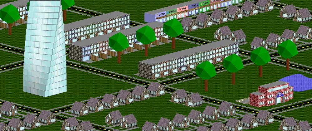
A JavaScript-free website that compresses down to 10 KB should offer peak performance, but a 3D city-building game is the exception. Performance issues aside, I am quite pleased with how many features are possible with native HTML/CSS 3D rendering.
The first half of this post is focused on converting .obj files into pure HTML/CSS elements, and this information is potentially useful even if you do not plan to make a city builder. The second half covers how to explore the city, customize the look, and track some metrics like population.
If you want to play you can try a variety of city sizes to find the right fit for your computer: 10x10, 8x8, 6x6, 4x4, or 2x2. Browsers are generally not optimized for the abuse I throw at them, so there is a lot of variability in performance. A decent laptop with Firefox is ideal, Chrome should be playable, Safari might be buggy, and phones are likely too small and underpowered.
Converting 3D objects to HTML
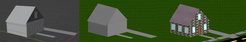
There are many programs that make it easy to generate and edit 3D objects. Since buildings can be fairly simple with lots of rectangles it is not too hard to automatically create an HTML element.
I settled on exporting to the .obj format since it seems common and easy to parse. CSS has a matrix3d() transform so once you get the vertices in (x,y,z) it is just about matrix arithmetic.
Matrix3d
An HTML element is a rectangle in 2D space and we will transform about the origin. The vertices will be (0,0,0), (0,h,0), (w,h,0), and (w,0,0) where w and h are the dimensions of the original rectangle.
For the following example, I will assume the height and width are 100 while the final 3D vertices are located at (100,100,-100), (150,150,-150), (200,150,-200), and (150,50,-150).
The matrix3d() operation is a 4x4 augmented matrix so we add a 1 as the 4th coordinate of each vertex. Then we need to compute the matrix M such that for all 4 vertices.
We will always have a 0 as the 3rd argument so the 3rd row of M shouldn't impact the computation. For some reason putting 0s in this row breaks things, but it doesn't seem to matter as long as the numbers are non-zero. I have had success making this row all 1s, but I don't know if there is some scenario where this row needs to be something particular.
Also, the final column should be (0,0,1,1). The fourth coordinate and fourth column are just there to allow for the translation row. The computation for the first vertex will look like this:
There are 9 unknown values in the matrix and we have 9 variables: 3 for each of 3 corners (the fourth corner of a rectangle is determined by the other 3). Ultimately there are enough 0s to make solving quite easy.
Using the 1st, 2nd, and 4th vertices to avoid the corner without any 0s, we end up with the following three equations:
Finally, convert the 4x4 matrix into a 1x16 by adding the top row in order and then proceeding to the next rows. Affine transformations are often performed with the matrix on the left (i.e ), but if you solve for that matrix then you would need to add by columns which is less intuitive.
.face {
  transform-origin: 0 0 0;
  transform-style: preserve-3d;
  /*transform: matrix3d(a,b,c,0,d,e,f,0,1,1,1,1,g,h,i,1);*/
  /*before solving above, after solving below*/
  transform: matrix3d(0.5,-0.5,-0.5,0,0.5,0.5,-0.5,0,1,1,1,1,100,100,-100,1);
}
Initial Rectangle
The .obj file will order the vertices so that the 1st and 3rd vertices are opposite corners. At a minimum, make sure to do the same with the inputs to avoid an incorrect transformation matrix.
For a horizontal texture like bricks, it is important to find the bottom. I reorder the vertices until the first two have the smallest y-coordinates. Then start the input vertices with the non-zero y-coordinates.
If you care about left vs. right and/or top vs. bottom then you may need to make further adjustments. Be aware that HTML and CSS view the positive y-axis as going down the screen. The .obj file includes lots of data that might be helpful if you know more than I do.
For any non-uniform texture, it is important to have the correct aspect ratio and desired size. The length of each side is the Euclidean distance ( ). Regardless of the original size, the element will be scaled to the same final size but the texture will be applied to the original.
Triangles
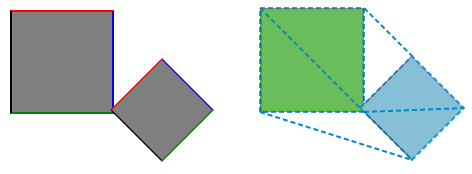
Any polygon is possible by drawing a rectangle that encloses the polygon and then using a clip-path. I may add more polygons if they are worth the trouble, but triangles are relatively simple to compute and can be combined to match or approximate any surface.
Computing both the enclosing rectangle and the clip-path starts by finding the point on one side that is closest to the third point. For simplicity, assume the triangle looks like below with the third point being closer to an interior point than either endpoint.
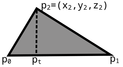
First, parameterize the line from to so that the coordinates of are . The value of that minimizes the distance to is
Then compute the vector . The four vertices of the rectangle will be . The third point will be of the way between the two new vertices so the clip-path will be polygon(0% 0%, 100% 0%, 100t% 100%, 0% 0%) (depending on the order of vertices you choose).
Shading
I ended up settling for a very basic shading scheme. The sides of buildings are shaded slightly to give some nice contrast, but the results are not realistic.
It is much simpler to set the shading without needing to know anything about other faces, so I judge whether a face is a side based on how much the x-coordinates change compared to the y- and z-coordinates.
//x is an array of all x-coordinates, etc...
x.sort(); let xd = x[x.length-1]-x[0];
y.sort(); let yd = y[y.length-1]-y[0];
z.sort(); let zd = z[z.length-1]-z[0];
let brightness = 70 + 20*xd/Math.min(yd,zd);
Determining whether a face is a front or back wall is not impossible, but if you don't get every face correct then the mismatched shading is much worse than unrealistic shading. The best approach is likely to determine the shading before generating the .obj file. You could just append a percentage in a way that is easy to parse and then turn that into different classes.
Materials
In Blender (and other programs, I assume) it is easy to set the material of each face. This information is included in the .obj file and can be easily added as a class name in CSS.
Then we just need to style each class to mimic the desired texture. I chose to use pure CSS for purity reasons and because it seemed absurd to add textures that doubled the size of the package, but you can certainly use either SVG or JPG patterns.
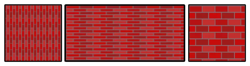
Most textures will be repeating and you need to set both the background-image and background-size properties. I have found it easiest to set the background-size in pixels and then scale the elements proportionally to make every brick in the city the same size.
.brick {
  background-image: url('brick.jpg');
  background-size: 20px 20px;
}
Many patterns can be made with pure CSS by using gradients, but you generally need to work for it. The problem is that gradients are limited to operating in 1 dimension so they need to be carefully layered to mimic 2 dimensions.
Even something simple like a brick pattern requires separate gradients for each angled half of a brick. If you don't want to figure out the trigonometry yourself, I created a basic CSS texture generator on Replit that you can use to make some simple patterns like bricks and stones.
Windows
It can be annoying to individually add a row of windows, but CSS can easily divide a whole row into a certain number of evenly spaced windows with flex.
We need to add enough child divs, but then the odd-numbered divs can have the desired window style while even-numbered divs are transparent. Setting the flex value will determine how much space there is between each window.
.window-split {
    display: flex;
    background: transparent;
}
.window-split > div:nth-child(2n-1) {
    background-color: hsl(180,50%,80%);
    flex: 2;
    border: 2px solid black;
}
.window-split > div:nth-child(2n) {
    flex: 1;
}
An entire row of windows only needs one 3d transformation, so I hope this method is more performant but I really don't know. There are potentially other ways to style an entire wall with child elements as long as you know the relative positions.
Making a City
To create an entire customizable city from our collection of buildings, I arrange buildings into predefined blocks. Then a large grid is added that players can click to change the type of block for each cell.
I use nunjucks and Node to generate XML and XSL files that can neatly generate the HTML for all of the possible blocks. The use of XSL means that the network weight is about 10 KB even though the generated HTML exceeds 10 MB. If you are willing to add client-side JavaScript then there are better options with more features, of course.
Ground Layer
Below all of the buildings lays the ground layer with grass, roads, and sidewalks. If we drop a div to the bottom and then rotateX(90deg), it will be in the right location. However, it will be invisible because we are looking at a flat object from the side.
We want to rotate the parent element so we don't see the buildings directly from the side, and setting rotateX(-15deg) on the parent will make the ground visible.
The easiest approach to make each block clickable and allow for roads and sidewalks is to add a separate ground div for each block. This div will have 4 child elements in order from bottom to top:
- a grass background-image
- a road border-image texture
- a sidewalk with top and bottom border-image textures
- a sidewalk with left and right border-image textures
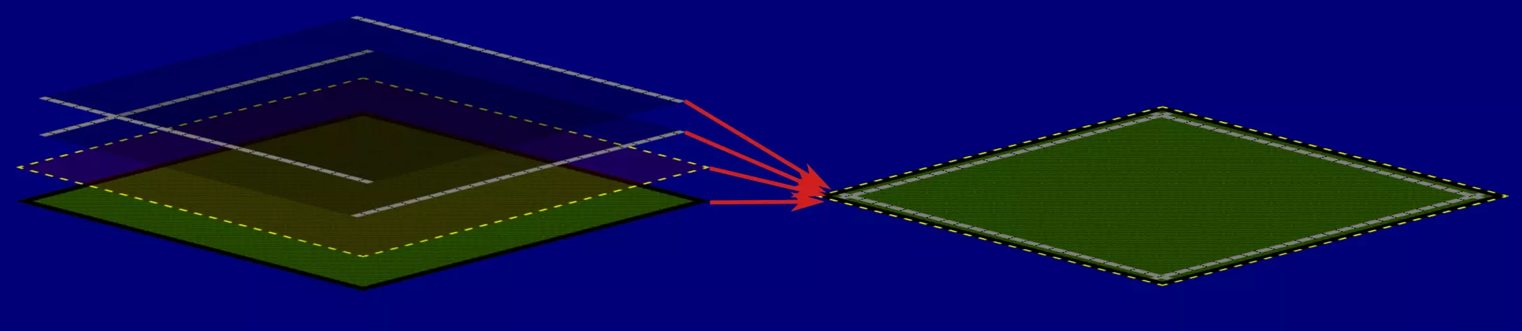
I added labels for each possible block type to the grass element. The corresponding radio buttons are much earlier in the DOM so that changes can be seen by any element.
Pointer events are turned off by default so that clicks pass through the buildings, but it is possible to turn on pointer events for child elements. The invisible labels are the only elements that are clickable on the map part.
Blocks of Buildings
Add a building by creating a node with the name of the building type and then add "x", "y", and "a" nodes for the location within the block as well as the angle of rotation. There is also an optional stats node that tracks the number of people who would live in that block or any other metric you wish to track.
<stats>
    <people>100</people>
</stats>
<townhouses>
    <x>2</x>
    <y>94</y>
</townhouses>
<townhouses>
    <x>98</x>
    <y>6</y>
    <a>180</a>
</townhouses>
<tree>
    <x>15</x>
    <y>53</y>
</tree>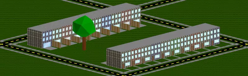
Once each block is generated it is added to the large grid and transformed to the desired location. The main downside of the block approach is that there is less room for variety, but it makes building out a city quick and painless.
Exploring
To see the city from different angles and locations, we need to properly set the transform-origin property of the parent element. I have found it best to set the origin to be in the middle of the bottom of the screen.
Zooming just requires adjusting the scale() factor while rotating adjusts rotateY(). The difficulty of avoiding JavaScript here is that each zoom level and rotation step requires its own radio button.
To make the menu nice we need to set the display type, location, and text for the previous and next options based on the current status of the buttons.
/*set the correct menu when the zoom is at level 3*/
#zoom-3:checked ~ .menu label[for=zoom-4] {
    display: block;
    left: 3.5rem;
}
#zoom-3:checked ~ .menu label[for=zoom-4]::before {
    content: "+";
}
#zoom-3:checked ~ .menu label[for=zoom-2] {
    display: block;
    left: 1rem;
}
#zoom-3:checked ~ .menu label[for=zoom-2]::before {
    content: "-";
}
To move the camera's location, there need to be radio buttons for each possible location. I have placed steps at every half block. When the player moves to a new location, CSS variables for the x and y locations are updated and then used in any element that needs that information.
Knowing where to move when the forward/backward/right/left button is clicked requires knowing both the current location and the current rotation. It ended up being easiest to create buttons for all of the possible combinations and then carefully display just the right four.
The checked location button triggers a parent div to be displayed. The checked rotation button displays four of the labels in every div and properly locates them, and the combined result is exactly what the player expects.
<!--buttons up here somewhere-->
<div class="cell-3-4">
  <label class="f1 b5 r7 l3" for="button-2-4"></label>
  <label class="f2 b6 r8 l4" for="button-2-5"></label>
  <label class="f3 b7 r1 l5" for="button-3-5"></label>
  <!--and 5 more-->
</div>
#button-3-4:checked ~ .cell-3-4 {
display: block;
}
#rotation-1:checked ~ div .f1 {
display: block;
top: 0;
left: 0;
}
#rotation-1:checked ~ div .r1 {
display: block;
top: 1rem;
left: 2rem;
}
/*and lots more combos, plus content*/The final challenge is that the map extends below the screen so tall buildings can still pop up into the visible portion. We must compute which buildings are behind the camera and set their opacity to zero.
CSS allows for trigonometric functions so it is a matter of getting the math right. We need a formula that is at least 1 when the building should be visible and less than 0 otherwise.
/*angle is the angle of rotation, x0 and y0 the center */
/*x and y are the location of the building*/
.box {
  /*sign hides top or bottom half depending on angle*/
  --sign: calc(abs(var(--angle) - 180) - 90);
  /*m is slope and b is intercept of dividing line*/
  --m: calc(tan(var(--angle) * 1deg));
  --b: calc(var(--y0) - var(--m) * var(--x0));
  opacity: calc(var(--sign) * (var(--m) * var(--x) + var(--b) - var(--y)));
}
If you wonder why two rotations don't produce exactly vertical lines, it is because I did not want to worry about adding cases to handle undefined values of arctangent properly so I offset those slightly.
Scoring
To really make it a game we need some scoring mechanism. The simplest approach is to use CSS counters. If we create a sequence of divs with one div for each cell in the grid, then we can increment the counter by a variable amount to produce a total population.
Checking a radio button changes the value of the corresponding cell to a predefined value for that block type. Once the counter has computed the sum, we need to add one more element at the end to capture that value and display it.
.parent {
  /* define values for each block type */
  --res-people: 100;
  --office-people: 0;
}
.cell {
  /* the value of the people will counter will be incremented by the value of the people variable */
  counter-increment: people var(--people);
}
#res-1-1:checked ~ .parent #cell-1-1.cell {
  /* set the value of the people variable */
  --people: var(--res-people);
}
#office-1-1:checked ~ .parent #cell-1-1.cell {
  --people: var(--office-people);
}
.output::after {
  content: counter(people);
}
This same group of divs can be used to compute multiple sums, like people, jobs, and money. The build process makes it easy to define the values for any metric within the definition of each block in XML.
Density Map
With a bit of filtering, we can make a map to roughly display the areas that have too much housing or not enough. The idea is to set the color of each cell in a grid based on the block type and then add a blur.
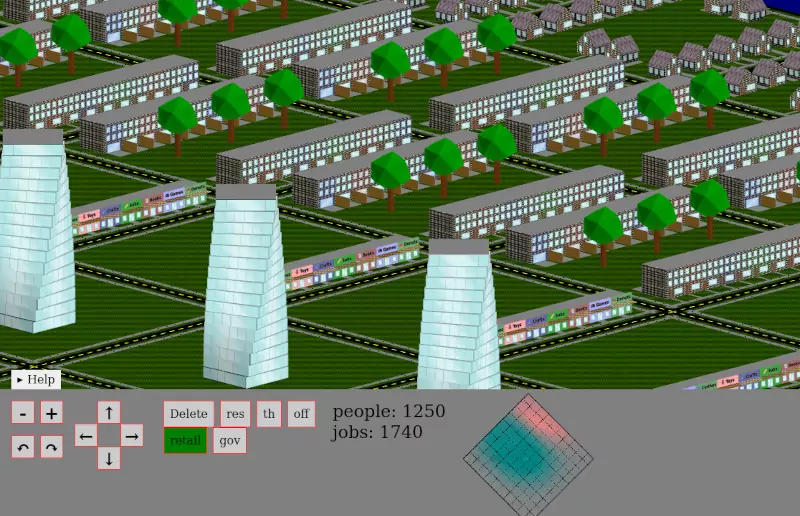
I have created a simple map of people versus jobs using RGB values with the green and blue values at 128 (halfway to the max of 255). Empty cells have a red value of 128, cells with lots of people have a larger red value, and cells with lots of jobs have a red value below 128. Color values are set with the same method as setting the score counter.
I set the blur value (the standard deviation for a Gaussian blur) to twice the size of a cell. Too many houses will make an area red while too many jobs will make the area blue-green. After blurring, it helps to increase the contrast to easily discern areas of concern. More complicated arithmetic is possible but there are limits to how smart these maps can get.
Future Development
While my main motivation was the challenge itself, the game turned out to be enjoyable and has the advantage of being relatively easy to modify. Fork the code on Replit to add your own buildings, edit materials, and arrange the blocks. I will try to update that repository and its readme to make everything more user-friendly over time.
If there is demand, I may create a version that uses a bit of JavaScript. I'm not sure how much performance would improve, though, without a complete rewrite to take advantage of WebGL. At a minimum, there would be more customization options which would be really nice for some variety.
On a more practical level, I will likely explore other uses of a .obj to HTML parser. While trying to build out an entire city of buildings is more intensive than I would like, a few 3D objects on a page are easy for browsers to render.
For now, though, I am mostly going to add some more buildings and assets. I am not an expert at generating 3D (or 2D) graphics so I do hope others can do better. Or if you're a novice looking for an excuse to get started with 3D graphics, a simple house was a great first project for me.